Gas turbine diagram Specific power turbine gas engine diagram turbines energy education powers aircraft because figure very they large Gas turbine diagram
K-Jetronic Fuel Injection System
Ge lm6000 (cf6-80c2) gas turbine Cross-sectional view of the gas turbine generator [diagram] gas turbine propulsion systems diagram
Gas turbine fuel system example
The schematic diagram for a simple gas turbine.Specific power Gas turbines – ryno drillingDownload jet engine processing.
High level view of a gas turbine fuel systemTurbine identification parametric fraction Gas turbines review: siemens, ge, ansaldo and mitsubishiSchematic diagram of a gas turbine engine..

Fuel cell-gas turbine diagram
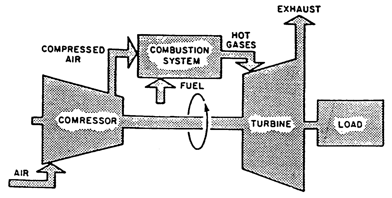
Simplified block diagram of a gas turbine.Schematic block diagram of gas turbine system 4 types of gas turbine engine components, work principlK-jetronic fuel injection system.
Gas turbine fuel engine control chemeng queensu ca savedAll about general electric pg 9171 e gas turbine Diagram block tm system fuel airTurbine gas patents system fuel control engine.
Fuel control in a gas turbine
System boundaries for lcaTurbine gas turbin combustion jet britannica major generators jenis How to choose the right gas turbine engineTurbine siemens turbines ansaldo schematic araner.
Patent us6487847[diagram] gas turbine compressor diagram Turbine generator sectionalInjection jetronic regulator accumulator valves innovationdiscoveries.

Fuel engine turbine schematic system control aircraft electronic assembly jet governor unit requirements oil air aviation pump systems power general
Gassturbinarbeid og typer – geoengineering norwayGas turbine diagram flow simple turbines electric cycle axial starting general support pg unit tutorials Gas turbine control systemBlock diagram of a simple gas turbine plant.
Turbine engine gas jet stages processing pngkitFigure 6-1. fuel system block diagram Car fuel system block diagram diesel[diagram] gas turbine propulsion systems diagram.

Gas-turbine engine
Aircraft systems: turbine engine fuel system—general requirementsTurbine turbines cooling 7mw combined mw Schematic diagram of a simple gas turbine power plantFigure 4-23. fuel system block diagram.
.


Schematic diagram of a gas turbine engine. | Download Scientific Diagram

Simplified block diagram of a gas turbine. | Download Scientific Diagram

Figure 4-23. Fuel System Block Diagram

Cross-sectional View of the Gas Turbine Generator | Download Scientific

Fuel Control in a Gas Turbine | Gas turbine, Turbine engine, Turbine

K-Jetronic Fuel Injection System

Aircraft systems: Turbine Engine Fuel System—General Requirements
