Engine using heat pv diagram Pv diagram turbocharged engine Ciclo diesel y ciclo otto
FUEL SYSTEM: COMPONENTS WORKING PRINCIPLES SYMPTOMS
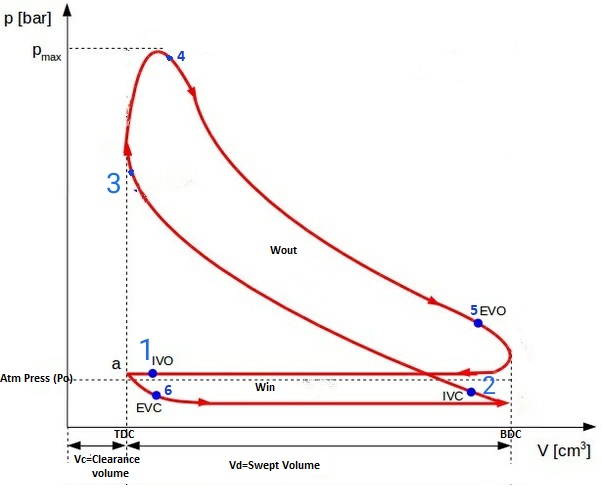
Turbine diagram gas cycle closed working pv various booster mechanical construction processes used Actual pv diagrams of 4 stroke and 2 stroke marine diesel engines Cycle d'otto idéal
Jet engine pv diagram
Solved: for the heat engine shown in the pv diagram below, 25,483Mechanical technology: sketch p-v diagram of petrol engine & diesel engine Turbine cycle brayton2 stroke engine pv diagram.
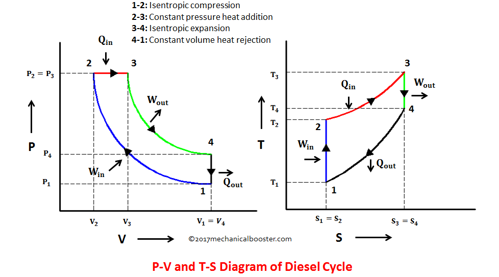
Closed cycle gas turbine: construction, working, diagramDiesel cycle: explanation, pv diagram, and efficiency Engine stroke cycle otto petrol plotting calculating matlabPv diagram: definition, examples, and applications.
Gasoline engineplete diagram and manual
Pv diagram for two stroke petrol engine – artofitFuel system: components working principles symptoms Diesel cycle diagram process processes four working booster mechanical easily grasped help theseGasoline engine diagram.
Piston engine thrust augmentationStroke pv actual engines diagrams diagram diesel engine cycle marine ic valves Gasoline terminology automotive bensin komponen stroke combustion timing kerja otto danI would like to make an interactive pv diagram (thermodynamics) however.

2 stroke petrol engine vs 4 stroke petrol engine
P-v diagram of 4Brayton cycle engine thrust nasa piston diagram turbine pv pressure volume plot augmentation thermodynamic Otto cycle tv diagramGasoline engine diagram.
Heat engine pv diagramOtto cycle pv engine stroke diagram pressure ideal volume motor ciclo isochoric gasoline diagrama process volumen ts two presion adiabatic Pv ts isochoric thermodynamic work cycles processes intake plots solve thermodynamicsCycle processes thermodynamic cycles thermodynamics nuclear.

Gasoline mesin combustion four genset prinsip pengertian piston generator pembakaran siklus bakar ilustrasi injeksi langsung langkah katup buang kerjanya
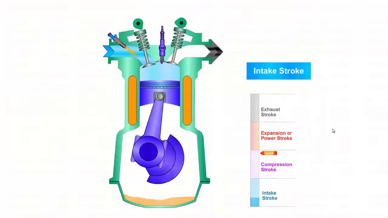
Pv and ts diagram of brayton cycle gas turbineEngine pv diagram animation Cycle diesel moteur diesel diagramme de volume de pression carburantOtto cycle.
Engine diesel diagram petrol cycle sketch pvDiesel cycle: learn the definition & working with pv-ts diagram Gasoline engines differ principles innovationdiscoveries controls emissionDiagram engine system gasoline fuel engines applsci g001 cylinder diesel text full wiring compression ignition sciences applied combustion navigation dual.
Diesel cycle – process with p-v and t-s diagram
Actual and ideal diesel cycleOtto cycle Gasoline engine diagramThe pressure-volume (pv) diagram and how work is produced in an ice – x.
Diesel engine diagram pv cycle air standard compression ratio theoretical wiring turbocharged typical gif4. fuel: the pv diagram above describes an engine Gasoline nxpGasoline engine diagram.

Pv brayton energy
.
.


Otto Cycle - pV, Ts Diagram | Application | nuclear-power.com

SOLVED: For the heat engine shown in the PV diagram below, 25,483

Ciclo diesel y ciclo Otto

Gasoline Engine Diagram

I would like to make an interactive PV diagram (thermodynamics) however
Gasoline Engineplete Diagram And Manual
